CAD discussion forum - ask any CAD-related questions here, share your CAD knowledge on AutoCAD, Inventor, Revit and other Autodesk software with your peers from all over the world. To start a new topic, choose an appropriate forum.
Please abide by the
rules of this forum.
This is a peer-to-peer forum. The forum doesn't replace the official direct technical support provided by ARKANCE for its customers.
How to post questions: register or login, go to the specific forum and click the NEW TOPIC button.
| Author |
 Topic Search Topic Search  Topic Options Topic Options
|
wtojp2013 
Newbie

Joined: 21.Oct.2013
Location: Hong Kong
Using: autocad
Status: Offline
Points: 8
|
 Topic: How to draw irregular shape Topic: How to draw irregular shape
Posted: 02.Apr.2014 at 06:26 |
Hi guys,
According to the provided information. How can I draw the shape ? Thank you.
Edwin
|
 |
philippe JOSEPH 
Senior Member

Joined: 14.Mar.2011
Location: France
Using: AutoCAD Mechanical 2017
Status: Offline
Points: 1481
|
 Posted: 02.Apr.2014 at 08:03 Posted: 02.Apr.2014 at 08:03 |
Hello wtojp2013, I supose that this is exactly a "parametric constrains" test for you.
I don't know all about this but having tried it, it looks like you have to deal with a formula inside it.
I have done a file with constraints, can we see yours before ?
Edited by philippe JOSEPH - 02.Apr.2014 at 10:50
|
 |
Kent Cooper 
Senior Member

Joined: 12.Mar.2013
Location: United States
Using: AutoCAD2020, 2023
Status: Offline
Points: 683
|
 Posted: 02.Apr.2014 at 15:12 Posted: 02.Apr.2014 at 15:12 |
This certainly doesn't do the whole thing for you, but it might give you something to start from:
|
 |
philippe JOSEPH 
Senior Member

Joined: 14.Mar.2011
Location: France
Using: AutoCAD Mechanical 2017
Status: Offline
Points: 1481
|
 Posted: 02.Apr.2014 at 15:47 Posted: 02.Apr.2014 at 15:47 |
Hello Kent and wtojp2013.
I have uploaded my test : SHAPE_01_A.dwg ( no chance with upload here ).
I'm not sure of it 100% because I don't know much about parametric constrain but I'm afraid that it did work
with nearly 2 clics with AUTOCONSTRAIN.
Maybe some parametric constrain specialst ( if exists ) could take a look and criticize it.
Edited by philippe JOSEPH - 02.Apr.2014 at 15:49
|
 |
dylhunter 
Newbie

Joined: 25.Mar.2014
Location: China
Using: AutoCAD2010
Status: Offline
Points: 10
|
 Posted: 02.Apr.2014 at 19:00 Posted: 02.Apr.2014 at 19:00 |

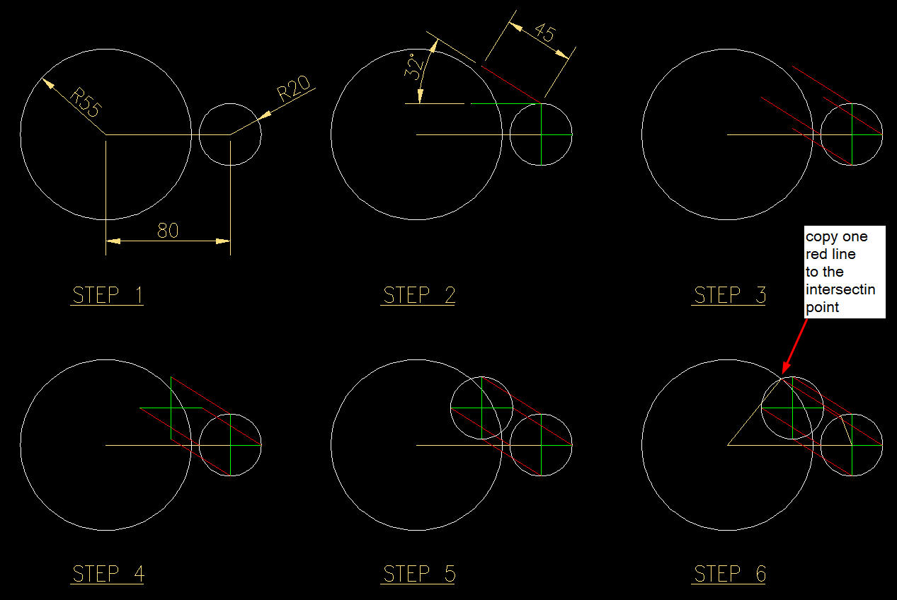
Hope it's helpful for you.
Thanks,
|
 |
philippe JOSEPH 
Senior Member

Joined: 14.Mar.2011
Location: France
Using: AutoCAD Mechanical 2017
Status: Offline
Points: 1481
|
 Posted: 02.Apr.2014 at 20:13 Posted: 02.Apr.2014 at 20:13 |
Hello dylhunter, your solution looks so simple that you could even go from step 2 to step 6 directly.
Edited by philippe JOSEPH - 02.Apr.2014 at 20:57
|
 |
dylhunter 
Newbie

Joined: 25.Mar.2014
Location: China
Using: AutoCAD2010
Status: Offline
Points: 10
|
 Posted: 02.Apr.2014 at 22:17 Posted: 02.Apr.2014 at 22:17 |
Yes. I just want to show the track of the end point. Actually, we can copy the dia. 22 circle to the end point of red line at step 3. then copy one red line to the intersection point. Done.
|
 |
dylhunter 
Newbie

Joined: 25.Mar.2014
Location: China
Using: AutoCAD2010
Status: Offline
Points: 10
|
 Posted: 02.Apr.2014 at 22:20 Posted: 02.Apr.2014 at 22:20 |
|
Sorry. Should be the rad. 20 circle. Not dia. 22 circle.
|
 |
wtojp2013 
Newbie

Joined: 21.Oct.2013
Location: Hong Kong
Using: autocad
Status: Offline
Points: 8
|
 Posted: 03.Apr.2014 at 05:38 Posted: 03.Apr.2014 at 05:38 |
dylhunter,
Thank you very much. This technique is very useful for me.
|
 |
philippe JOSEPH 
Senior Member

Joined: 14.Mar.2011
Location: France
Using: AutoCAD Mechanical 2017
Status: Offline
Points: 1481
|
 Posted: 03.Apr.2014 at 07:51 Posted: 03.Apr.2014 at 07:51 |
dylhunter and wtojp2013, I'd say that wtojp2013 and my method work the same in 2 steps.
wtojp2013 is purely geometry and works 100% without any problem.
It should be prefered to mine but if not applicable to a purely geometrical solution you could test it ( see the file : SHAPE_01_A.dwg in the AutCAD blocks library and tell me about it ).
|
 |
 Discussion forum
 CAD discussion forum - ask any CAD-related questions here, share your CAD knowledge on AutoCAD, Inventor, Revit and other Autodesk software with your peers from all over the world. To start a new topic, choose an appropriate forum.


![CAD Forum - tips, tricks, discussion and utilities for AutoCAD, Inventor, Revit and other Autodesk products [www.cadforum.cz] CAD Forum - tips, tricks, discussion and utilities for AutoCAD, Inventor, Revit and other Autodesk products [www.cadforum.cz]](/common/arkance_186.png)


 How to draw irregular shape
 Topic Options


