


 Discussion forum
|

 CAD discussion forum - ask any CAD-related questions here, share your CAD knowledge on AutoCAD, Inventor, Revit and other Autodesk software with your peers from all over the world. To start a new topic, choose an appropriate forum.
Please abide by the rules of this forum.
How to post questions: register or login, go to the specific forum and click the NEW TOPIC button.


How to Draw Wave-Alike Object? |
Post Reply 
|
Page <123> |
| Author | |
dery 
Senior Member 
Joined: 31.Jan.2018 Location: United States Using: AutoCAD 2014 Status: Offline Points: 114 |
 Post Options Post Options
") Thanks(0) Thanks(0)
 Quote Reply Quote Reply
 Posted: 13.Apr.2024 at 17:58 Posted: 13.Apr.2024 at 17:58 |
|
I can do draw the arc, draw the arrowhead, and join the line thing. The one that I can't do is drawing the slanted tangent.
Edited by dery - 13.Apr.2024 at 18:02 |
|
 |
|
|
Kent Cooper
Senior Member
Joined: 12.Mar.2013 Location: United States Using: AutoCAD2020, 2023 Status: Offline Points: 631 |
Post Options
Thanks(0)
Quote Reply
Posted: 13.Apr.2024 at 18:51 |
|
Draw two Circles. Position them as appropriate. Draw a Line using TANgent Object Snap for both ends. Mirror the Line across each Circle's CENter point. Trim out the unneeded parts of the Circles.
Or, draw a regular zig-zag of Lines. Draw Circles with the TTR [Tangent-Tangent-Radius] option into the corners [experiment with the needed radius]. Trim out the unneeded parts of the Circles and the Lines. Or, with some care about positional Snap, you could just draw the whole thing as a Polyline directly, alternating between Line and Arc modes -- starting an arc segment off the end of a line segment defaults to tangent continuation from the line.
Edited by Kent Cooper - 13.Apr.2024 at 19:20 |
|
|
|
|
Kent Cooper
Senior Member
Joined: 12.Mar.2013 Location: United States Using: AutoCAD2020, 2023 Status: Offline Points: 631 |
Post Options
Thanks(0)
Quote Reply
Posted: 13.Apr.2024 at 19:14 |
For the linetype-based approach: Copy and Paste the ARC150 Shape definition from my 4th post into a plain-text editor such as Notepad, and Save it to a file with a .SHP filetype ending [call it whatever you want]. I think you need to make sure the file does not end at the end of the code content, but on an empty line below that [Enter to get that if needed -- depends on how you Copied the definition from here]. In AutoCAD, use the COMPILE command on it, to make a file with the same name but a .SHX filetype ending. Copy and Paste the Linetype definition (in my 1st post) into a plain-text editor and Save it to a file with a .LIN filetype ending. Change the red part to the name of your compiled Shape file. I think likewise the file needs to end with an empty line. In AutoCAD, use the LINETYPE command's Load option, and the File button to get to your file, to load the linetype. Apply it to things just as you would AutoCAD's standard linetypes. Note that at an effective linetype scale of 1, each bulge of the S-waving is 2 drawing units wide [the height is a little less than the 1 unit in the ARC180 definition]. You will need to apply a linetype scale to get them the size you want. In use as a Leader, the Dimension Style and Dimension Scale determine the size of the arrowhead, but the S-wave size is independent of the arrowhead size -- you can control them separately. It's easier if you put both files into some location where AutoCAD knows to look [see the Support File Search Path list in the Files tab in the OPTIONS dialog box]. [If you really need tangent line bits between the ends of the arcs, that can be done with a slightly longer Shape definition.]
Edited by Kent Cooper - 13.Apr.2024 at 19:17 |
|
|
|
|
dery
Senior Member
Joined: 31.Jan.2018 Location: United States Using: AutoCAD 2014 Status: Offline Points: 114 |
Post Options
Thanks(0)
Quote Reply
Posted: 13.Apr.2024 at 19:31 |
|
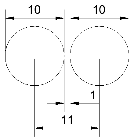
How do you draw the slanted line that tangent to the two circles like this?
 Edited by dery - 13.Apr.2024 at 20:02 |
|
|
|
|
Kent Cooper
Senior Member
Joined: 12.Mar.2013 Location: United States Using: AutoCAD2020, 2023 Status: Offline Points: 631 |
Post Options
Thanks(0)
Quote Reply
Posted: 16.Apr.2024 at 19:17 |
|
As I described before, simply draw a Line using TANgent Object Snap for both ends. You can pick anywhere on the Circles that's reasonably close to where the real tangent points will be, and AutoCAD will work it out.
 Edited by Kent Cooper - 16.Apr.2024 at 19:25 |
|
|
|
|
dery
Senior Member
Joined: 31.Jan.2018 Location: United States Using: AutoCAD 2014 Status: Offline Points: 114 |
Post Options
Thanks(0)
Quote Reply
Posted: 17.Apr.2024 at 04:35 |
|
Does what I'm doing is same as the one on the pic or there is something else that more similar and accurate with the one on the pic?
Edited by dery - 17.Apr.2024 at 05:19 |
|
|
|
|
Kent Cooper
Senior Member
Joined: 12.Mar.2013 Location: United States Using: AutoCAD2020, 2023 Status: Offline Points: 631 |
Post Options
Thanks(0)
Quote Reply
Posted: 17.Apr.2024 at 18:33 |
|
There is no more accurate way to do it than the Line using TANgent Osnap for both ends.
|
|
|
|
|
dery
Senior Member
Joined: 31.Jan.2018 Location: United States Using: AutoCAD 2014 Status: Offline Points: 114 |
Post Options
Thanks(0)
Quote Reply
Posted: 18.Apr.2024 at 02:55 |
|
So do you mean that what I'm doing is the same as the one on the pic?
|
|
|
|
|
Kent Cooper
Senior Member
Joined: 12.Mar.2013 Location: United States Using: AutoCAD2020, 2023 Status: Offline Points: 631 |
Post Options
Thanks(0)
Quote Reply
Posted: 19.Apr.2024 at 14:54 |
|
[You have not yet actually said "what [you're] doing," nor to which "pic" you are referring.]
Edited by Kent Cooper - 19.Apr.2024 at 15:12 |
|
|
|
|
dery
Senior Member
Joined: 31.Jan.2018 Location: United States Using: AutoCAD 2014 Status: Offline Points: 114 |
Post Options
Thanks(0)
Quote Reply
Posted: 19.Apr.2024 at 17:05 |
|
What I mean with "what I'm doing" is on the 4th post on this page (page 2).
And what I meant with the "pic" is on the 1st post on page 1. So? What is your answer regarding my question on post #8 and page 2? |
|
|
|
 Topic Options
 dery wrote:
|
Post Reply
|
Page <123> |
 Tweet
Tweet
|
| Forum Jump | Forum Permissions You cannot post new topics in this forum You cannot reply to topics in this forum You cannot delete your posts in this forum You cannot edit your posts in this forum You cannot create polls in this forum You cannot vote in polls in this forum |
This page was generated in 0,375 seconds.
|
CAD Forum - tips, tricks, utilities, discussion for AutoCAD, LT, Inventor, Revit, Map, Civil 3D, 3ds Max, Fusion 360 and other Autodesk software (support by Arkance Systems)
|
Arkance Systems CZ (CAD Studio) - Autodesk Platinum Partner & Training Center & Services Partner
|
CONTACT:
webmaster.cz@arkance-systems.com tel. +420 910 970 111 |
|
| Copyright ©2024 | Advertise with us | Online privacy |
| ||
