 CAD tip # 7481:
Question
Symbols are contained in most fonts and you can access them through Unicode codes. But you need to use a "rich" font containing the requested symbol. The Truetype font Arial (Arial.ttf) is one of such fonts - and Arial is the default font used in the predefined style "Standard" in newer versions of AutoCAD. So we can avoid referring a specific style in the linetype definition, and first of all avoid creating the specific style in all drawings which should use the newly defined linetype.
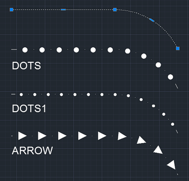
Examples of such symbol linetypes are these dotted (spotted) and arrow-type linetypes:

*DOTS,Dots .  .  .  .  .  .  .  .  .  .  .  .  .  .  .  .  .  .
A,.000001,-3,["\U+25CF",Standard,S=3,R=0,X=-1.25,Y=-1.25],-3
*DOTS1,Dots1 .  .  .  .  .  .  .  .  .  .  .  .  .  .  .  .  .  .
A,.000001,-3,["\U+2022",Standard,S=3,R=0,X=-1.44,Y=-1.44],-1.7
*ARROW,Arrow1  >  >  >  >  >  >  >
A,.000001,-3,["\U+25BA",Standard,S=3,R=0,X=-1.35,Y=-1.35],.000001,-4
You can also download it HERE
You can add these definitions to your ACADISO.LIN (or ACAD.LIN) file, or you can save them to a separate LIN file. You can load a .LIN file into an AutoCAD DWG drawing with the LINETYPE command.
The spacing between symbols is controlled by the negative values in the definition. The symbol size is controlled by the linetype scale property. The small dots between symbols are neccessary as the linetype definition must start with a full line segment.
We recommend to use the "Linetype generation" property for polylines (PLINEGEN=1).
![CAD Forum - tips, tricks, discussion and utilities for AutoCAD, Inventor, Revit and other Autodesk products [www.cadforum.cz] CAD Forum - tips, tricks, discussion and utilities for AutoCAD, Inventor, Revit and other Autodesk products [www.cadforum.cz]](../common/arkance_186.png)


