With a simple iLogic macro (rule) you can pseudo-randomly change shape of Inventor parts, their appearance, or geometry and appearance of complete assemblies. Assigning random values to dimensional parameters can help when creating architectural (e.g. facade) elements, designer components of consumer products, or in other creative experiments.
The core of such dynamic designs is driving dimensional parameters by iLogic rules and using the functions Rnd(), resp. Randomize(). You can of course control any type of parameter - fillet radius, number of array elements, bending angle, etc. For the specific macro code, see below.
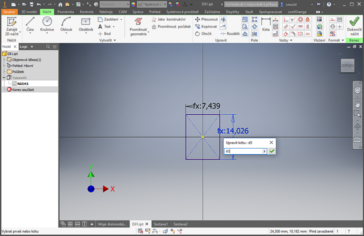
Let us first create the basic 3D model. We will use a simple box, sizes of its sides will change randomly (independently), but their average sizes will be close to the ratio 1:2:3. Start with a 2D sketch in the XY plane, a centered rectangle - so that the box position will not jump when its size is changing. The rectangle sides will be driven by the parameters d0 and d1:
For the same reason, we will use the option "Symmetric" for the Extrusion of the sketch. The extrusion size will be driven by the parameter d3:

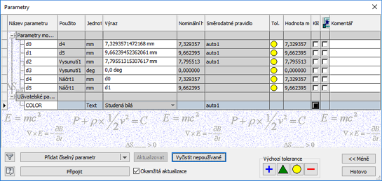
We will make the random sizing more attractive by randomly changing also the appearance (color) of the part. To achieve this, open the Parameters dialog and create a custom text-based parameter COLOR - this parameter will be then fully driven from the iLogic rule:
Now create the iLogic macro (called "auto1" here) in your IPT document. It fills three dimensional parameters with random values from the interval 0-10, 0-20 and 0-30 (the Randomize command ensures unique values on each run). Then fill the variant parameter COLOR from the asortiment of appearances available in the current document and select a random appearance from this list. Assign this appearance as a new color to the current (resized) part:
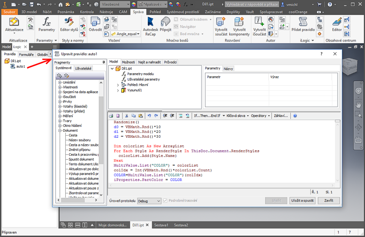
NOTE: the macro code can be found in the sample IPT part Dil1.ipt in the Block catalog.
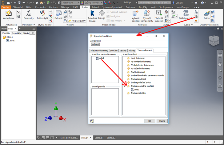
So that the macro "auto1" will be run on every update of the part, assign it (by mouse dragging in the direction of the red arrow) to the event "Change of the part geometry":
The resulting behavior of the dynamic part can be verified by repeated invoking of the function "Rebuild all":

Let's try now to use our random part in an IAM assembly. Insert multiple occurrences of the Díl1.ipt part to a different fixed positions (no constraints) into a new assembly. The function "Rebuild all" - applied in an assembly - again creates a pseudo-randomly generated shapes and appearances, but you can see, that the single source of the part geometry results in a single, unified appearance of all its occurrences in the assembly:

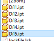
If you need to have all assembly parts in their own, individual appearance and size, you will first need to copy the Dil1.ipt file to multiple individual copies and then combine them by inserting/placing into a single assembly.
An assembly with individually placed copies of the original part now behaves quite differently when rebuilt repeatedly:

![CAD Forum - tips, tricks, discussion and utilities for AutoCAD, Inventor, Revit and other Autodesk products [www.cadforum.cz]](../common/arkance_186.png "CAD Forum - ARKANCE Community - tips, tricks, discussion and utilities for AutoCAD, Inventor, Revit and other Autodesk products [www.cadforum.cz]")

 CAD tip # 12046:

